Hardware Preparation and Use
This part describes how to use the hardware from the user's point of view. It explains what function the LEDs have and how to use connectors and interfaces. It also explains what additional equipment you will need to use the modem.
LEDs
The mainboard (MB) has six LEDs indicating the status of the modem.

| LED | Color | Function | Description |
|---|---|---|---|
| LD5 | Orange | Battery level | Displays the status of the battery (see battery-level code table) |
| LD4 | Red | AGC on | Lit when AGC (automatic gain control) is enabled. |
| LD3 | Yellow | Serial RX | Toggles when a UART packet from the host has been received successfully. |
| LD2 | White | Acoustic TX | Lit while transmitting an acoustic packet. |
| LD1 | Green | Acoustic RX | Toggles upon successful reception of an acoustic packet. |
| LDP | Blue | Power on | Lit when the 3.3V supply voltage is available1. |
The battery-level LED has the following blink pattern to indicate the battery status.
| Blink Code | Status |
|---|---|
 |
Excellent, 75-100% |
 |
Good, 50-75% |
 |
Low, 25-50% |
 |
Critical, 0-25% |
 |
Too high |
Info
The indicator levels are rough estimates based on a 3S LiPo battery with 11.1V nominal and 12.6V maximum rating. They incorporate the voltage drop of the protective diode.
Connectors
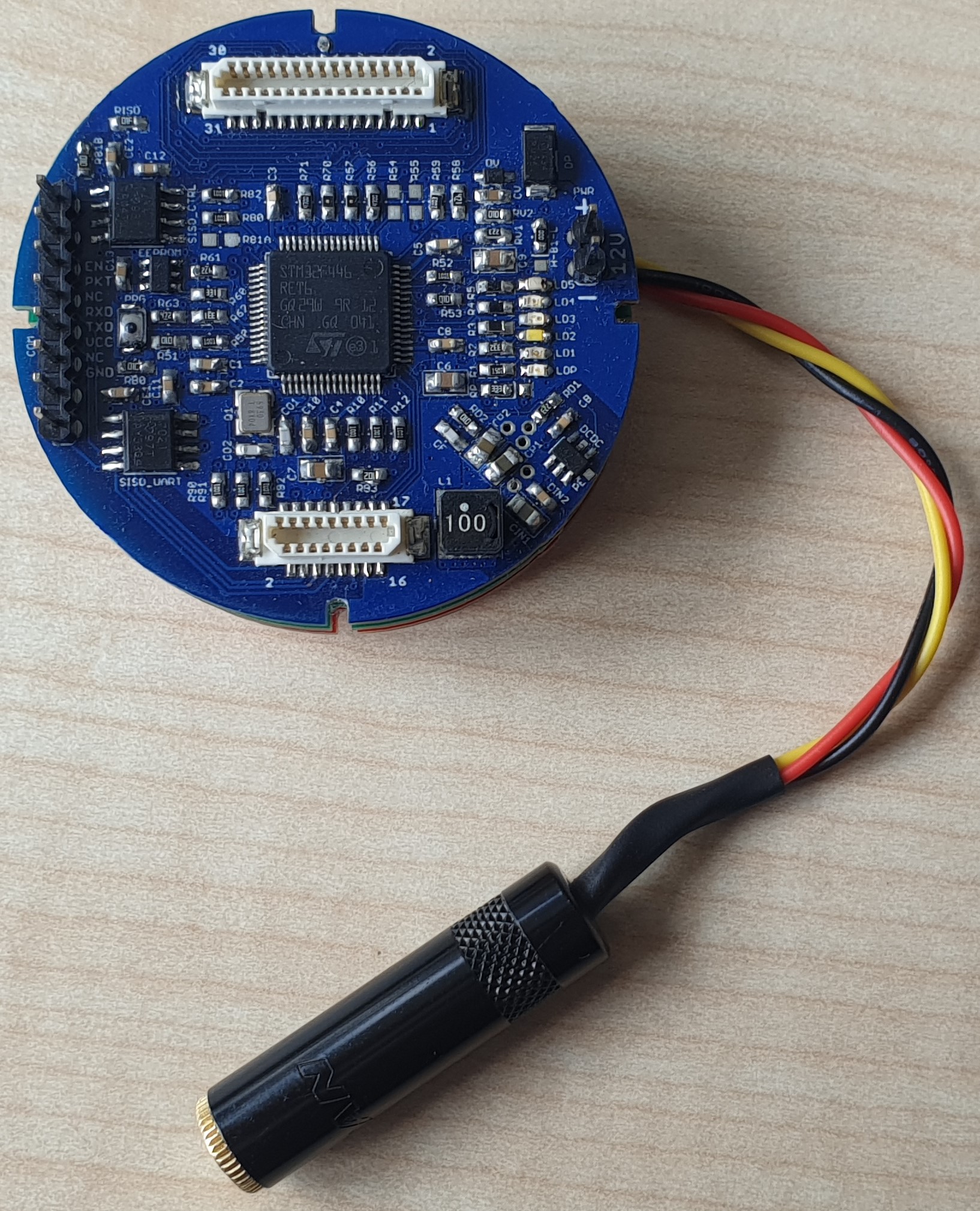
Mainboard MB
The mainboard is the main interfacing part of the ahoi acoustic modem. It comprises two pin header connectors, one for power supply (C1) and one for external I/O (C2).

Power Supply
C1: Supply (Pin header 2.54mm)
| Pin | Signal | Description |
|---|---|---|
| 1 | GND | Power ground |
| 2 | Vin | Positive power (12V or 3S battery) |
Info
Connector (C1) powers the modem in all operation modes (including firmware updating / programming). This power connector is the only one that is reverse voltage protected.
Danger
The modem accepts any input voltage from 10 to 13 V. Exceeding this range may cause permanent damage to the device.
External I/O
C2: External I/O (Pin header 2.54mm)
| Pin | Signal | Type | Description |
|---|---|---|---|
| 1 | WUP | input | Modem wake-up from sleep via rising edge2 |
| 2 | PKT | output | Packet available indicator. This pin is logic high, while a packet is available on the modem3 |
| 3 | NC | Not connected | |
| 4 | RXD | output | UART isolated receive data (receive line of host) |
| 5 | TXD | input | UART isolated transmit data (transmit line of host) |
| 6 | VCC | power | External positive power for isolated UART and IO lines |
| 7 | NC | Not connected | |
| 8 | GND | power | External power ground for isolated UART and IO lines |
Info
The external I/O connector is used for communication between host and modem. All lines are isolated, so that external power is required. We recommend to use 3.3V input voltage and logic levels; however, the isolators have a maximum rating of 5.5V.
Transmitter TXB or TX

C3: Hydrophone Connector
| Pin | Signal | Description | 1-wire Connection | 2-wire Connection |
|---|---|---|---|---|
| 1 | HCON+ | Hydrophone positive (hot) | + | + |
| 2 | CABLE_GND | Shielding | NC | S |
| 3 | HCON- | Hydrophone negative (cold) | -/S | - |

The hydrophone is connected to C3 as depending on its cable configuration. If the hydrophone cable has
- a single wire and shield, connect the wire to HCON+ and the shield to HCON-; do not connect HSHIELD on the TX board.
- two connection wires and a separate shield, connect the hot wire to HCON+ and the cold wire to HCON-; connect the shield to HSHIELD on the TX board.
Warning
The hydrophone must be connected to the TX board.
Accessories
In this section, we list and explain the additional equipment you need in addition to the three PCBs.
Hydrophone
The ahoi modem uses a piezo-electric device, such as a hydrophone or piezo disc, for communication. It is optimized for an AS-1 hydrophone from Aquarian Audio. However, it is possible to use a different device instead. Please refer to the Customization chapter, if you plan to use a different device.

Hydrophone Connectors
At the moment, four different connectors are used to connect a hydrophone to the ahoi modem:
- 3-pin JST PH connector with 2mm pitch for PCB connection
- 3-pole 3.5mm phone connector respectively tip, ring, sleeve (TRS) connectors for inside connections
- 3-pin Weipu SP13 Series connectors for weatherproofed connections
- 3-pin Blue Trail Cobalt Connector for underwater connections (connectors have 600 meters depth rating)
The mapping depends on the hydrophone cable configuration (see Transmitter TXB or TX).
Two-Wire Cable with separate Shield
| Signal | Typ. Cable Color | Hydro Cable | JST PH | TRS | SP13 | Cobalt |
|---|---|---|---|---|---|---|
| HCON+ | red | + | Pin 1 | Tip | Pin 3 | Pin 2 RED |
| HCON- | yellow | - | Pin 3 | Ring | Pin 2 | Pin 3 YELLOW |
| CABLE_GND | black | S | Pin 2 | Sleeve | Pin 1 | Pin 1 BLACK |
Single-Wire Cable with Shield serving as Cable Ground
| Signal | Typ. Cable Color | Hydro Cable | JST PH | TRS | SP13 | Cobalt |
|---|---|---|---|---|---|---|
| HCON+ | red | + | Pin 1 | Tip | Pin 3 | Pin 2 RED |
| HCON- | yellow | S | Pin 3 | Ring | Pin 2 | Pin 3 YELLOW |
Warning
In the case of the single-wire connection do not connect CABLE_GND. If you are using the bridge transmitter (TXB) and connect the shielding to CABLE_GND, your modems transmit with only 25% of the output power (50% output voltage). If you connect the shielding to HCON- and CABLE_GND, your modems get destroyed due to a short circuit on the transmitter board.
Examples
| Modem with TRS | JST PH to TRS Adapter |
|---|---|
 |
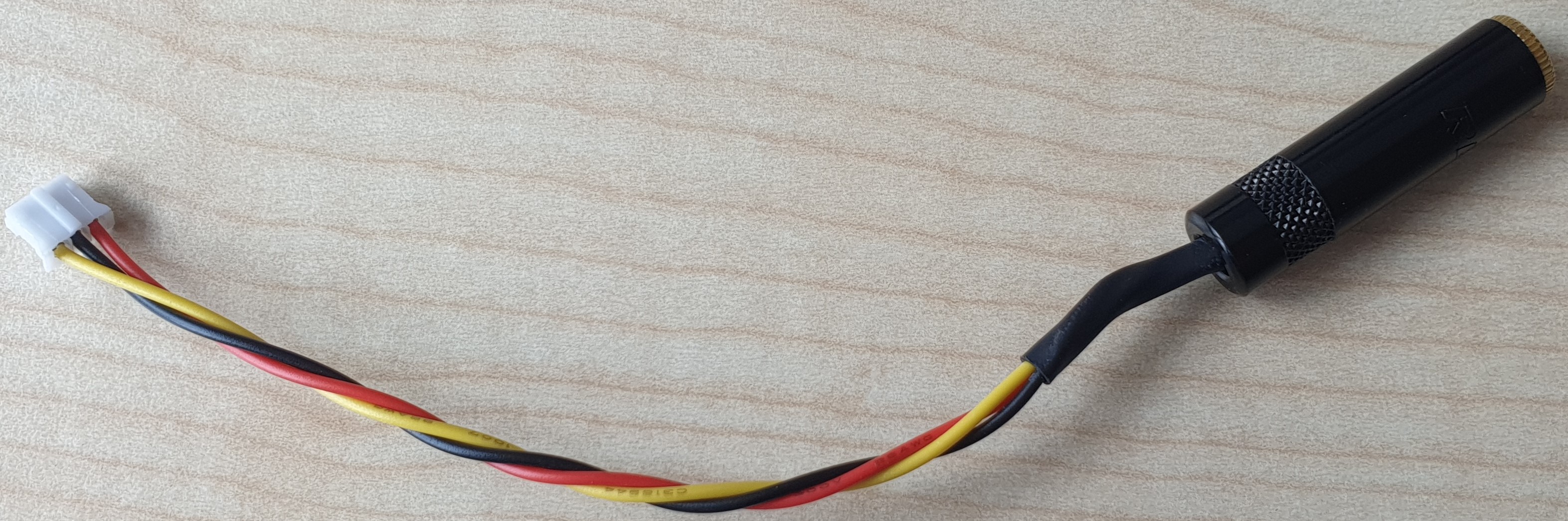 |
| Hydrophone and Blue Robotics End Cap with Cobalt Connector | TRS to Cobalt Adapter integrated into the End Cap |
|---|---|
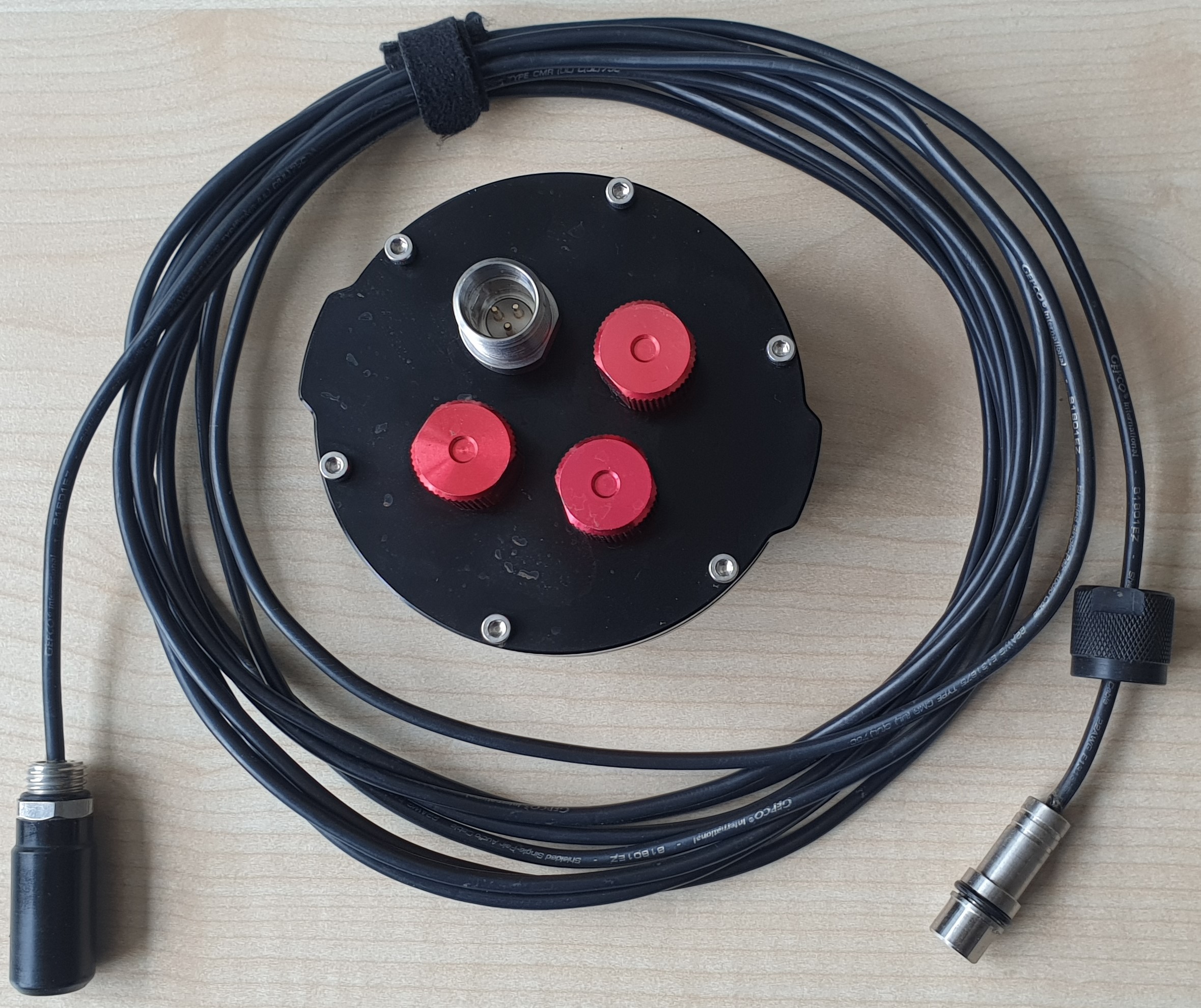 |
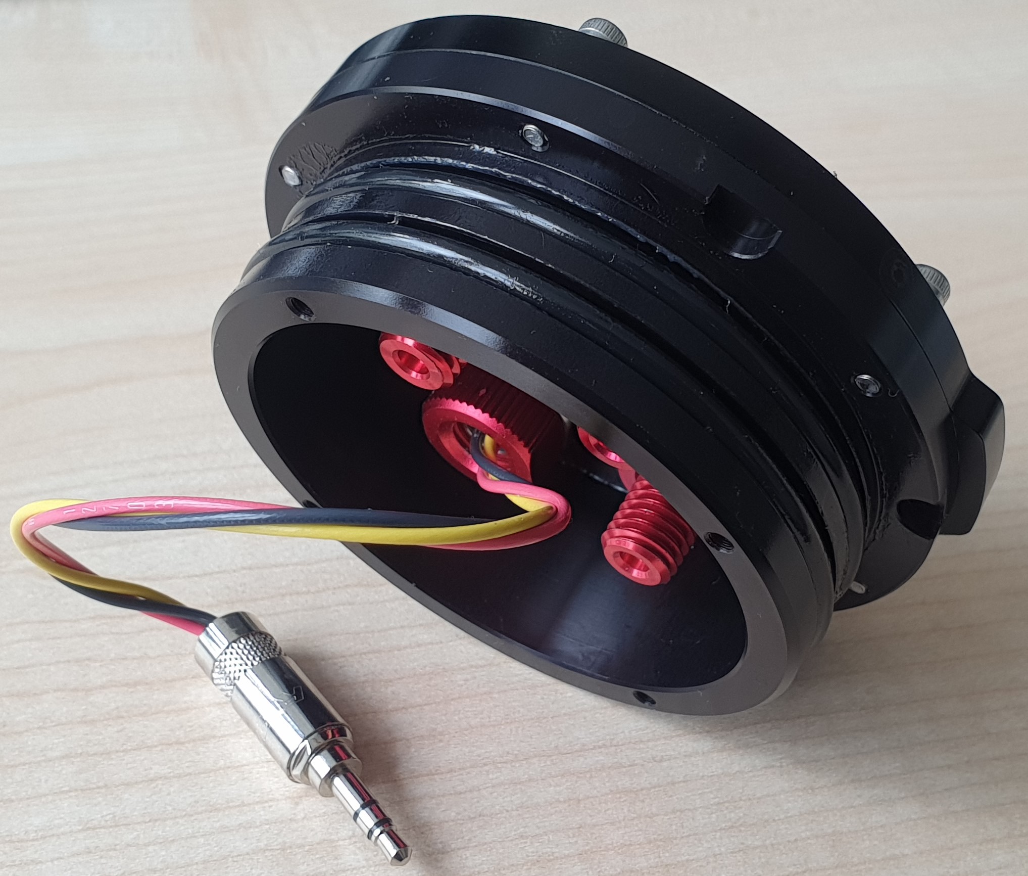 |
Power Supply
The modem is designed to work with 3-cell (3S) Lithium-Polymer-Accumulator (LiPo) batteries. If you use one with a JST BEC connector, you can connect this battery directly to the supply pin header (C1) on the mainboard.

Alternatively, you can also use a 12V power supply; e.g., a bench power supply. It may be convenient to build an adapter cable from 4mm Banana to 2.54mm pin header.

Unfused
The modem has no integrated fuse. Be careful when the battery is connected. Short circuits will cause permanent damage the board, and may set the battery on fire or cause explosion.
Add a fuse or use the current limit of your power supply to avoid damage or danger.
Serial Communication
To communicate with the modem, a USB-to-serial adapter is required. The external I/O connector (C2) is designed to accept a TTL-232R-3V3 adapter with 6-pin female connector directly.
