
Dynamics of the separation characteristics of flow classifying processes
- Institute:
Institut für Mechanische Verfahrenstechnik, TU Clausthal
- Project leader:
Prof. Dr. rer. nat. Alfred P. Weber, TU Clausthal
- Researcher:
M. Sc. Christian Spötter, TU Clausthal
Introduction
In process engineering the classification processes of dry solids is of great importance for the separation of misplaced particles (e.g. behind a mill) and for the production of particle fractions with a narrow particle size distribution [1]. In the last decades the deflector wheel classifier has been established as one of the most important classifiers in the field of air separation machines. The deflector wheel classifier is a counter-flow centrifugal classifier with a forced eddy-sink-flow. The deflector wheel classifier has largely replaced the spiral air classifier because of its lower sensitivity to changes in solids loading. In a deflector wheel classifier a rotor generates the circumferential component of the flow and ensures its persistence irrespective from the used material charge. Classifying air and charging materials are fed together or separately into the classification zone. Due to their high centrifugal forces FZ the coarse particles remain on the outer circumference of the deflector wheel and are separated from this point into the coarse fraction. They are proverbially deflected by the classifying wheel, which led to the denomination “deflector wheel classifier”. The fine particles are transported from the air into the area between the deflection paddles and are sucked centrally into the fine particle tube due to the dominating drag force FD [2]. The theoretical cut size xt,th can be calculated by using the force equilibrium between the drag and centrifugal force at the outer radius R0 of the deflector wheel (Figure 2, right side.) which gives the equation (1):
\[ x_{t,th}=\sqrt{\frac{18 \eta \cdot v_{r,0}\cdot r_0}{\rho_p \cdot v_{\phi 0}^2}} \]
with the circumferential and radial velocity $v_{\phi 0}$ and $v_{r,0}$, the dynamic viscosity of the air $\eta$ and the density of the solid $\rho_p$.
Project objective
The dynamic separation behaviour of air flow classifying processes for dry particles will be described as part of this project. The focus will be on the consideration of the non-stationary operation process with high particle loadings. As example, the separation process of a deflector wheel classifier will be investigated. On the one hand, the effects of rapidly changing operating parameters on the classification process must be investigated. On the other hand, a time-resolved sampling should provide information on the transition from non-stationary to stationary condition. The aim is the development of a time and place resolved model for the description of the separation process. In this case, the separation behaviour and the process quality are described as a function of feed material flow, particle size distribution, loading as well as particle-particle- and particle-paddle-interactions.
The expansion of the existing model approach (in stationary condition) for describing the dynamic separation behaviour involves the implementation of the hold-up (fine particle ring in the periphery of the deflection wheel), the particle streaks (in the periphery) and the time constants for the formation of a stationary separation process. A coupling of the microscope high-speed camera with DEM simulations (Discrete Element Method) is intended to provide information about the relationship between the revolution rate of the deflection wheel and the between the paddles occurring air vortex as well as for the measurement of process parameters.
Work program
To simplify the already complex studies the experiments are carried out using a particle collective with a closely distributed particle size distribution. A non-adhesive limestone is used as feed material. The focus is on the extension of an already established numerical model (trajectory model) from stationary to dynamic non-stationary conditions. The overall objective is to develop a flowsheet for the deflector wheel classifier that takes all components that influences the dynamic separation process into account. This model must then be integrated into the Dyssol-program as a module. Since some components of the module, such as a hold-up, must also be considered in other projects of the SPP, the implementation has to be carried out in close coordination with other project groups (WG: Wirth, Nirschl and Kruggel-Emden). Furthermore, the effect of high loadings on the particle movement around and in the deflector wheel should be understood in more detail.
The contemporary models are showing weaknesses especially at high loadings. The measurements have shown that, for a deeper understanding, the periphery around the deflector wheel and, in particular, the movement of the fine particles must also be described. On the one hand, investigations with a microscope high-speed camera as well as with a Laser Doppler Anemometer (LDA) should provide information about the revolution rate dependent velocities of the real separation process. On the other hand, the effective viscosity, which has so far been used as fit parameter, must be related to the particle loading and revolution rate. For this purpose, the experiments should be compared with DEM-Simulations with a strong variation of loading and revolution rate. From this comparison, knowledge about the approach and return velocity of particles immediately before and after the collision with the deflector wheel paddle can also be obtained. The resulting model must be integrated into a flow sheet diagram for describing the dynamic behaviour of a deflector wheel classifier. As the experiments in non-stationary conditions have shown, the classifier requires up to 50 minutes until it reaches steady state conditions. These time constants must be reproduced correctly in a dynamic overall model into which, in addition to the trajectory model, the previous findings on the formation of particle streaks, accumulation in a hold up ring and for air sighting in the periphery are also reflected correctly. This model must finally be implemented in co-operation with the work group of Prof. Heinrich in Dyssol (Z-project).
Material und method
The Hosokawa Alpine ATP 50
In order to determine the separation characteristics the modified deflector wheel classifier type Turboplex ATP 50 from Hosokawa Alpine with an aero cyclone and a bag filter system was used, as illustrated in Fig. 1 [3-4].
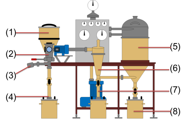
As feed material limestone (CaCO3) is introduced into the deflector wheel classifier (2) below the rotor via a screw conveyor which is attached to the side of the deflector wheel classifier (1). The cumulative particle size distribution of the feed material has a x10,3 of 5.86 µm, a x50,3 of 59.86 µm and a x90,3 of 179,54 µm. From the bottom of the housing the classifying air is supplied into the deflector wheel classifier tangential via an air pipe (3) which is equipped with a filter. The aspirator produces a constant air flow of 75 m3/h. The classifying wheel of the Turboplex ATP 50 has a wheel diameter of 50 mm and is powered by a horizontally positioned shaft. The peripheral speed of the separating wheel was varied over a frequency converter from 7.86 m/s (3000 rpm) to 39.27 m/s (15000 rpm). The rejected coarse material leaves the separator downwards through the central particle lock system outlet (4). The fine material leaves the classifier wheel together with the classifying air flows via a hollow shaft and a subsequent fixed pipe. The fine particle fraction is separated from the classifying air by an aero cyclone (6). The fine particles are leaving the cyclone through a particle lock system into fines outlet 1 (7). The ultrafine fraction leaves the aero cyclone via the vortex finder and is finally separated in a bag filter system (5). The bag filters are periodically cleaned with compressed air and the particles are collected in a fine outlet 2 (8) [3-4].
Reconstruction of the deflector wheel classifier for an optical accessibility
To determine the separation characteristics of a deflector wheel classifier the ATP 50 must be reconstructed so that an optical access onto the deflector wheel was achieved, however, maintaining the flow and classification conditions and the geometry of the classifying wheel and its surrounding components. In order to realize this, the motor of the wheel and the outlet pipe of the fine particle fraction had to be moved to the same side of the deflector wheel. The outlet pipe of the fine particles has been realized using a hollow shaft supported by two high-speed spindle bearings (Fig. 2 A), driven by a flat belt (B) which is sealed with an oil-soaked gasket. The drive of the hollow shaft takes place via a 1:3 gearing which is powered by a frequency-controlled three-phase asynchronous motor (D) (see Fig. 2) [3-4].
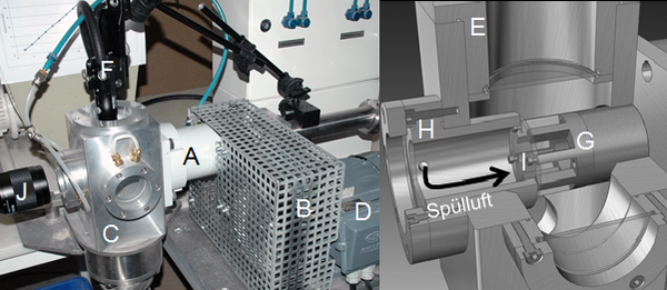
For the optical access to the classifier wheel specially designed viewing windows were installed on the top (E) and on the side (H). The windows were placed in the side wall and the ceiling of the housing. Special glass discs of the type Mirogard were used for the windows exhibiting anti-reflective properties on both sides leading to a high transparency. A high-speed camera Keyence VW-600M was placed in front of the window (cf. Fig. 2 (J)) to visualize the motions of the particles during the separation process. In order to prevent light reflections, the camera was aligned in a 90° angle to the illumination realized with a tripod lamp across the ceiling window [3-4].
Results
Visualization of the separation air and particle movement in the separation zone
In this experiments very fine limestone tracer particles (x50.3 = 2.15 μm) were used for the visualization of the air flow in the separation zone (between two separation wheel paddles). In addition, larger limestone particles (x50.3 = 59.86 μm) were used to make the particle movement visible. The movement of the fine particle accumulation is shown in Fig. 3 by arrows [3-5].
At a revolution rate of 3000 rpm, the tracer particles pass through the entire separation zone in an arc-shaped flow (Fig. 3 a)). Because of their higher inertia the coarse limestone particles follow the air flow initially into the separation zone (Fig. 4 a)), where they are carried more slowly radial inwards so that they are apparently focused on the outer edge of the pursuing paddle. The distribution of the particles across the separation zone is at this revolution rate is at least for fine particles relatively homogeneous [3-5].
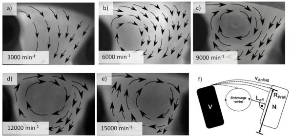
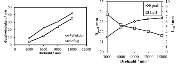
At higher revolution rates, an air vortex is formed between the paddles (Fig. 3 b-e). In order to parametrize the position of the vortex and its effect on the movement of the coarser particles, the two parameters Leff, which indicates the shortest distance between the vortex and the pursuing paddle, and RImp, which describes the distance from the separation wheel axis to the center point of the particle impact area, Fig. 3 f), are measured. With an increasing revolution rate, the separating vortex increasingly moves nearer to the pursuing paddle [3-5].
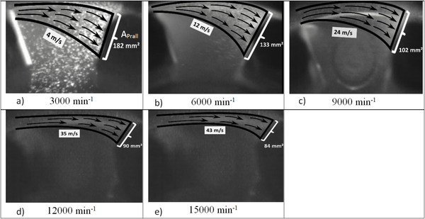
This leads to a constriction of the separation air flow and thus to an increased air flow velocity, which increases the drag force. Furthermore, the constriction of the separation air flow leads to an increasing focusing effect of the feed particle flow on an impact area which is reduced in a revolution rate dependent manner. The center point of the impact area is displaced with increasing revolution rate to the outside edge of the deflection wheel (see Figs. 4 b-e and Fig. 3 f). The influence of the revolution rate on the velocities of approaching and reflecting particles as well as on the effective length Leff and the impact radius RImp is shown in Fig 5. From the measured approaching and returning velocities of the particles (Fig. 5 a), an average coefficient of restitution of 1.39, could be measured. This means that in the absolute coordinate system, the particles experience a pulse transmission through the impact with the pursuing paddle so that they move faster than before. At low revolution rates, the particles are following the widely spread air flow to the inside of the separation zone before they interact with the pursuing paddle (particle-wall collision). This is much less the case at higher revolution rates [6].
Separation behavior at low material loadings
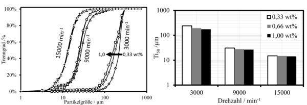
In Fig. 6 the measured separation effects are shown at three low material loadings for different revolution rates. While an increase of the revolution rate by a factor of 3 (from 3000 rpm to 9000 rpm) results in a decrease of the cut size by 86% (see Fig. 6 (right)), a rise in the material loading by a factor of 3 (from 0.33 wt% to 1.00 wt%) leads only in a reduction of the cut size by a few percent. Compared to the cut size, however, the separation sharpness is only slightly influenced by the material loading and revolution rate. For a limestone feedstock with an average particle size of 59 μm, the separation sharpness fluctuates by only a few percent with a mean value of 60 % at a revolution rate above 3000 rpm. For a revolution rate of 3000 rpm, where no air vortex has been formed between the paddles, the separation sharpness varies in a range of approximately 10 % compared to the average value of 60% [6].
Separation characteristics at high material loadings in stationary conditions
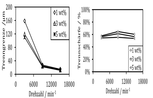
For the studies of the separation characteristics at high material loadings in stationary conditions, coarse and fine material samples were taken and analyzed by means of a time-resolved sampling system. In Fig. 7 (left), the cut size is plotted as a function of the revolution rate. While the cut size, as expected, is strongly dependent on the revolution rate and significantly less on the material loading, the separation sharpness (Fig. 7 (right)) remains remarkably unaffected by the operating conditions and fluctuates little by an average value of 60 %. A literature research (not shown here) has shown that other types of deflection wheel classifiers also produce an almost equal separation sharpness under the same or similar operating conditions. The reason for the invariance of the separation sharpness of many deflector wheel classifiers is still unclear. This work point must be studied in further experiments in combination with DEM simulations [4].
Streak formation in the periphery of the deflector wheel
The high-speed camera experiments at high material loadings have shown for the first time the formation of particle streaks in the periphery of the deflector wheel under real process conditions. Depending on the peripheral speed, streaks are formed that vary in type, size and residence time. The formation of streaks is determined on a periodic detachment of small streaks from the deflector wheel, which are later agglomerated to larger streaks before they leave the deflection periphery. At a revolution rate of 3000 rpm, the deflected particles are forming a primary streak at the outer edge of the pursuing paddle, which has an arched structure (Fig. 8) [7].
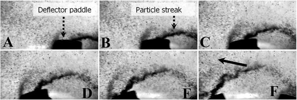
Due to the tangential detachment of the large streaks, collisions with feed particles have a significant influence onto the separation process. This influence must be studied in further experiments, supported by DEM-simulations. Even if the process is stationary, the separation process is constructed from unstable micro processes through the periodic formation and the detachment of these streaks. However, this periodical streak formation process is on a time scale in the kHz range and is not responsible for the observed start-up time until stationary operations are reached. This is rather a consequence of the material ring which forms around the deflector wheel and assumes the function of a hold-up [7].
References
- Leschonski K. Windsichter, verfahrenstechnische Maschinen zur Herstellung definierter pulverförmiger Produkte, Braunschweig, Jahrbuch der Wissenschaftlichen Gesellschaft, (1988)
- Legenhausen K. Untersuchung der Strömungsverhältnisse in einem Abweiseradsichter, Clausthal, Fakultät für Bergbau, Hüttenwesen, und Maschinenwesen, (1991)
- Spötter C., Legenhausen K., Weber A.P., Separation characteristics of a deflection wheel classifier in stationary conditions and at high loadings: New insights by flow visualization, KONA Powder and Particle Journal (akzeptiert am 19.09.2016)
- Spötter C., Stender M. Legenhausen K., Weber A.P. Dynamische Trenncharakteristik von Abweiseradsichtern, Produktgestaltung in der Partikeltechnologie, Fraunhofer Verlag, 405-421, Stuttgart (2015)
- Stender M. Legenhausen, K. Weber, A.P., Visualisierung von Partikelbewegungen in einem Abweiseradsichter, Chem. Ing. Tech. 87 (10), 1392-1401, (2015)
- Spötter C., Elskamp F., Hennig M., Teipel U., Weber A.P., Kruggel-Emden H. DEM-Simulation von Trennfunktionen für Trockenklassierprozesse in Siebung und Gegenstromsichtung bei geringen Gutbeladungen, Chem. Ing. Tech. (eingereicht am 26. 10. 2016)
- Spötter C., Legenhausen K., Weber A.P., Visualization of particle movements in the periphery of a deflector wheel classifier, AICHE Annual Meeting 2016, Conf. Proceedings AICHE Journal, (2016)